29. AUDIO CIRCUIT
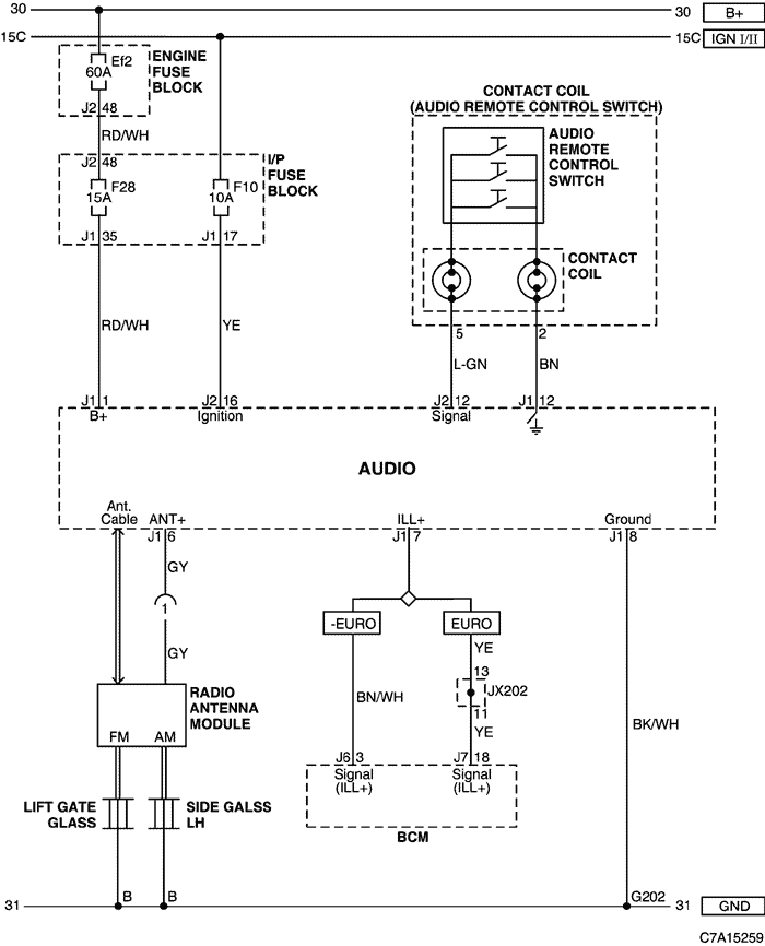
1) power supply, ground, remote control switch, antenna module circuit
a. CONNECTOR INFORMATION
connector no
(pin no, color) |
connecting wiring harness |
connector position |
| G202 |
I/P |
On the I/P Fuse Block braket |
b. CONNECTOR IDENTIFICATION SYMBOL & PIN NUMBER POSITION
c. POSITION OF CONNECTORS AND GROUNDS
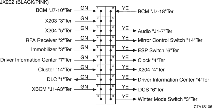
d. SPLICE PACK
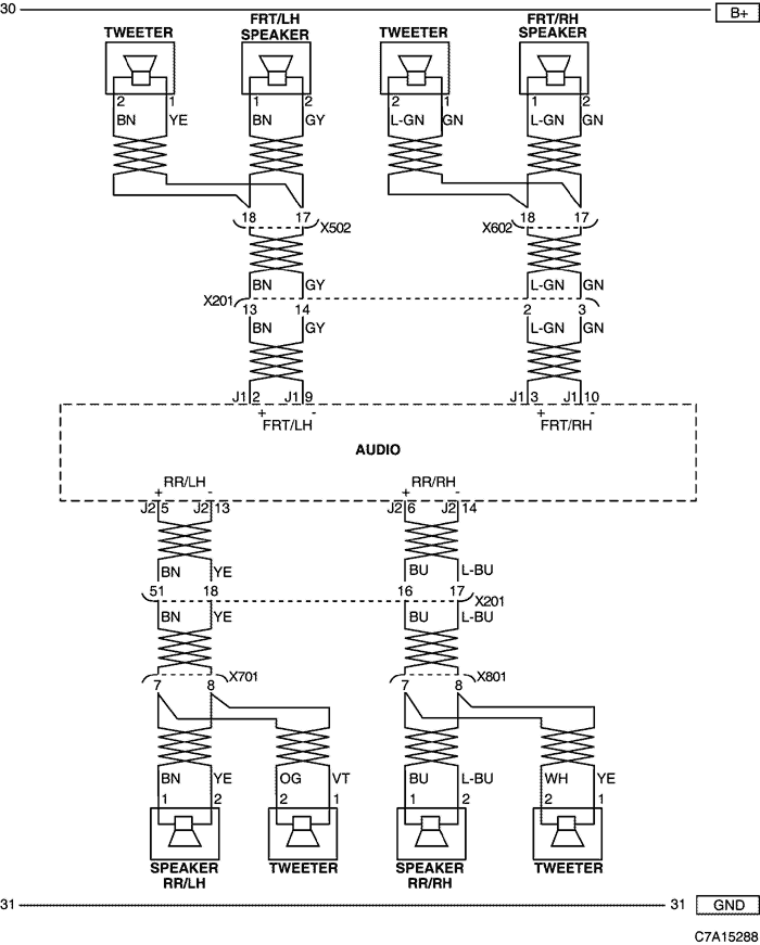
2) front/rear speaker, tweeter circuit
a. CONNECTOR INFORMATION
connector no
(pin no, color) |
connecting wiring harness |
connector position |
| X201 (92 Pin, Black) |
Body - I.P |
Below to the "A" pillar |
| X502 (18 Pin, Colorless) |
Body - Front LH Door |
Under the left "A" Pillar |
| X602 (18 Pin, Colorless) |
Body - Front RH Door |
Under the right "A" Pillar |
| X701 (15 Pin, Colorless) |
Body - Rear LH Door |
Under the left "B" Pillar |
| X801 (15 Pin, Colorless) |
Body - Rear RH Door |
Under the right "B" Pillar |
b. CONNECTOR IDENTIFICATION SYMBOL & PIN NUMBER POSITION
c. POSITION OF CONNECTORS AND GROUNDS
| https://vnx.su/ 🛠 Руководства по ремонту и эксплуатации для автомобилей |
Поиск по сайту
Остались вопросы или пожелания? Пишите на почту: support@vnx.su