Diagnostics in this manual assume a certain skill level and knowledge of Ford-specific diagnostic practices.
REFER to:
Diagnostic Methods
(100-00 General Information, Description and Operation).
Diagnostics in this manual assume a certain skill level and knowledge of Ford-specific diagnostic practices.
REFER to:
Diagnostic Methods
(100-00 General Information, Description and Operation).
for information about these practices.
Diagnostics in this manual assume a certain skill level and knowledge of Ford-specific diagnostic practices.
REFER to:
Diagnostic Methods
(100-00 General Information, Description and Operation).
for information about these practices.
PINPOINT TEST A : ENGINE DOES NOT CRANK (WITHOUT PUSH BUTTON START)
| A1
PERFORM INSPECTION AND VERIFICATION
|
|
NOTE:
Make sure battery voltage is greater than 12.2 volts prior to and during this pinpoint test.
NOTE:
If it is necessary to leave the battery charger connected during testing, do not leave it on its highest or boost setting.
The highest settings can exceed 16 volts, resulting in false test results and setting of Diagnostic Trouble Codes (DTCs).
-
Perform Inspection and Verification procedure in this section.
Was an obvious cause for an observed or reported concern found?
| Yes
|
Correct the cause as necessary.
|
|
| A2
RETRIEVE DTCS
|
-
Using a diagnostic scan tool, perform self-tests for:
Are any Diagnostic Trouble Codes (DTCs) present?
| Yes
|
For all
Diagnostic Trouble Codes (DTCs),
REFER to: Automatic Transmission (307-01 Automatic Transmission - Vehicles With: 6-Speed PowerShift Transmission - DPS6/6DCT250)
.
For
P0850, GO to
A6
For
P0830, GO to
A21
For all other
Diagnostic Trouble Codes (DTCs) GO to
A3
For all
Diagnostic Trouble Codes (DTCs) Refer to the BCM DTC Chart in this section.
|
|
| A3
CHECK THE PCM (POWERTRAIN CONTROL MODULE)
ENGINE CRANKING (ENG_CRANK) PID (PARAMETER IDENTIFICATION)
|
-
Using a diagnostic scan tool, view the
Parameter Identifications (PIDs).
-
For automatic transmission, make sure the transmission is in PARK or NEUTRAL.
-
For manual transmission, fully apply the clutch pedal.
-
Using a diagnostic scan tool, view the
ENG_CRANK, while holding the key in the START position.
Does the
ENG_CRANK change from Inactive to Active?
| Yes
|
For automatic transmission, GO to
A6
For manual transmission, GO to
A11
|
|
| A4
CHECK THE CRANK DETECT CIRCUIT FOR VOLTAGE AT THE PCM (POWERTRAIN CONTROL MODULE)
|
-
While holding the key in the START position, measure:
|
Positive Lead
|
Measurement / Action
|
Negative Lead
|
|
C175B-9
|

|
Ground
|
Is the voltage greater than 11 volts?
|
| A5
CHECK THE IGNITION SWITCH
|
-
Carry out the Ignition Switch Component Test.
Refer to Wiring Diagrams Cell 149 for schematic and connector information.
Did the ignition switch pass the component test?
| Yes
|
REPAIR circuit CDC35 (BU/WH) for an open.
|
| No
|
INSTALL a new ignition switch.
REFER to:
Ignition Switch
(211-05 Steering Column Switches, Removal and Installation).
|
|
| A6
CHECK THE TCM (TRANSMISSION CONTROL MODULE)
TR_CRANK PID (PARAMETER IDENTIFICATION)
|
-
Using a diagnostic scan tool, while viewing the
TR_CRANK, place the gear selector in PARK and then NEUTRAL.
Does the
TR_CRANK read YES in both positions?
| No
|
Diagnose the
sensor,
REFER to: Diagnosis By Symptom (307-01 Automatic Transmission - Vehicles With: 6-Speed PowerShift Transmission - DPS6/6DCT250)
.
|
|
| A7
CHECK THE PCM (POWERTRAIN CONTROL MODULE)
IN_GEAR PID (PARAMETER IDENTIFICATION)
|
-
Using a diagnostic scan tool, view the
Parameter Identifications (PIDs).
-
While observing the
IN_GEAR, place the gear selector in PARK and then NEUTRAL.
Does the
read No in both positions?
|
| A8
CHECK THE PARK/NEUTRAL CIRCUIT FOR A SHORT TO VOLTAGE
|
-
Measure:
|
Positive Lead
|
Measurement / Action
|
Negative Lead
|
|
C175T-4
|
|
Ground
|
Is any voltage present?
|
| A9
CHECK THE PARK/NEUTRAL CIRCUIT FOR AN OPEN
|
-
Measure:
|
Positive Lead
|
Measurement / Action
|
Negative Lead
|
|
C175T-4
|

|
C1750A-39
|
Is the resistance less than 3 ohms?
|
| A10
CHECK THE PARK/NEUTRAL CIRCUIT FOR A SHORT TO GROUND
|
-
Measure:
|
Positive Lead
|
Measurement / Action
|
Negative Lead
|
|
C175T-4
|
|
Ground
|
Is the resistance greater than 10,000 ohms?
|
| A11
CHECK THE PCM (POWERTRAIN CONTROL MODULE)
CLUTCH PEDAL AT OR NEAR BOTTOM OF TRAVEL (CPP_BOT) PID (PARAMETER IDENTIFICATION)
|
-
Using a diagnostic scan tool, while viewing the
CPP_BOT, fully apply the clutch pedal and release.
Does the
change from NO to YES when the clutch pedal is fully applied?
|
| A12
CHECK THE STARTER RELAY CONTROL OPERATION
|
|
NOTICE:
The following step uses a test light to simulate normal circuit loads. Use only the test light recommended in the Special
Tools table at the beginning of this section. To avoid connector terminal damage, use the Flex Probe Kit for the test light
probe connection to the vehicle. Do not use the test light probe directly on any connector.
-
Remove the
starter relay.
-
Measure:
|
Positive Lead
|
Measurement / Action
|
Negative Lead
|
 starter relay pin 1
|

|
starter relay pin 2
|
-
For automatic transmission , make sure the transmission is in PARK or NEUTRAL.
-
For manual transmission , fully apply the clutch pedal.
-
While holding the key in the START position, observe the test light.
Does the test light illuminate when the key is in the START position?
|
| A13
CHECK THE VOLTAGE TO THE STARTER RELAY
|
-
Measure:
|
Positive Lead
|
Measurement / Action
|
Negative Lead
|
|
starter relay pin 3
|
|
Ground
|
Is the voltage greater than 11 volts?
| No
|
VERIFY
fuse 10 (30A) is OK. If OK, REPAIR the circuit for an open. If not OK, REFER to the Wiring Diagrams manual to identify the
possible causes of the circuit short.
|
|
| A14
CHECK THE STARTER MOTOR OPERATION AT THE STARTER RELAY
|
-
With the transmission in PARK or NEUTRAL, momentarily connect a fused jumper wire:
|
Positive Lead
|
Measurement / Action
|
Negative Lead
|
|
starter relay pin 3
|

|
starter relay pin 5
|
Did the starter engage and the engine crank?
| Yes
|
INSTALL a new starter relay.
|
|
| A15
CHECK THE BATTERY GROUND CABLE
|
-
Measure:
|
Positive Lead
|
Measurement / Action
|
Negative Lead
|
|
|
Ground G100
|
Are the voltages greater than 11 volts?
| No
|
CLEAN or INSTALL a new negative battery cable as necessary.
|
|
| A16
CHECK THE STARTER MOTOR GROUND
|
Is the voltage greater than 11 volts?
| No
|
CLEAN the starter motor mounting flange and MAKE SURE the starter motor is correctly mounted.
|
|
| A17
CHECK THE VOLTAGE TO THE STARTER MOTOR
|
-
Measure:
|
Positive Lead
|
Measurement / Action
|
Negative Lead
|
|
C197A-1
|
|
Ground
|
Is the voltage greater than 11 volts?
| Yes
|
INSTALL a new starter,
REFER to:
Starter Motor
(303-06A Starting System - 1.6L Duratec-16V Ti-VCT (88kW/120PS) - Sigma, Removal and Installation).
|
| No
|
CLEAN the High current
connection to the battery post. CLEAN or REPAIR a positive battery cable as necessary.
|
|
| A18
CHECK FOR START INPUT AT THE STARTER
|
-
Disconnect Starter solenoid C197B
.
-
NOTE:
For manual transmission, fully apply the clutch pedal.
While holding the key in the START position, measure:
|
Positive Lead
|
Measurement / Action
|
Negative Lead
|
|
C197B-1
|
|
Ground
|
Is the voltage greater than 11 volts?
| Yes
|
CLEAN the starter solenoid "S" terminal and starter solenoid connector. CHECK the wiring and the starter motor for a loose
or intermittent connection.
|
| No
|
REPAIR the circuit for an open.
|
|
| A19
CHECK THE PCM (POWERTRAIN CONTROL MODULE)
STARTER RELAY CIRCUITS FOR A SHORT TO GROUND
|
-
Measure:
|
Positive Lead
|
Measurement / Action
|
Negative Lead
|
|
C175E-15
|
|
Ground
|
|
C175E-32
|
|
Ground
|
Are the resistances greater than 10,000 ohms?
| No
|
REPAIR the affected circuit.
|
|
| A20
CHECK THE PCM (POWERTRAIN CONTROL MODULE)
STARTER RELAY CIRCUITS FOR AN OPEN
|
Are the resistances less than 3 ohms?
| No
|
REPAIR the affected circuit.
|
|
| A21
CHECK THE CPP (CLUTCH PEDAL POSITION)
SWITCH
|
-
While fully applying the clutch pedal, measure:
|
Positive Lead
|
Measurement / Action
|
Negative Lead
|
|
C175E-14
|
|
Ground
|
Is the resistance less than 3 ohms?
|
| A22
CHECK THE CPP (CLUTCH PEDAL POSITION)
GROUND CIRCUIT FOR AN OPEN
|
-
Disconnect
switch C2353
.
-
Measure:
|
Positive Lead
|
Measurement / Action
|
Negative Lead
|
|
C2353-2
|
|
Ground
|
Is the resistance less than 3 ohms?
|
| A23
CHECK THE CPP (CLUTCH PEDAL POSITION)
SWITCH CIRCUIT FOR AN OPEN
|
-
Measure:
|
Positive Lead
|
Measurement / Action
|
Negative Lead
|
|
C175E-14
|
|
C2353-1
|
Is the resistance less than 3 ohms?
| Yes
|
INSTALL a new
switch.
REFER to:
Clutch Pedal Position (CPP) Switch
(303-14A Electronic Engine Controls - 1.6L Duratec-16V Ti-VCT (88kW/120PS) - Sigma, Removal and Installation).
|
|
| A24
CHECK FOR CORRECT PCM (POWERTRAIN CONTROL MODULE)
OPERATION
|
-
Disconnect and inspect all
connectors.
-
Repair:
-
corrosion (install new connectors or terminals - clean module pins)
-
damaged or bent pins - install new terminals/pins
-
pushed-out pins - install new pins as necessary
-
Reconnect the
connectors. Make sure they seat and latch correctly.
-
Operate the system and determine if the concern is still present.
Is the concern still present?
| Yes
|
CHECK
for any applicable Technical Service Bulletins (TSBs). If a
exists for this concern, DISCONTINUE this test and FOLLOW the
instructions. If no Technical Service Bulletins (TSBs) address this concern, INSTALL a new
.
REFER to:
Powertrain Control Module (PCM)
(303-14A Electronic Engine Controls - 1.6L Duratec-16V Ti-VCT (88kW/120PS) - Sigma, Removal and Installation).
|
| No
|
The system is operating correctly at this time. The concern may have been caused by module connections. ADDRESS the root cause
of any connector or pin issues.
|
|
PINPOINT TEST B : ENGINE DOES NOT CRANK (WITH PUSH BUTTON START)
| B1
PERFORM INSPECTION AND VERIFICATION
|
|
NOTE:
Make sure battery voltage is greater than 12.2 volts prior to and during this pinpoint test.
NOTE:
If it is necessary to leave the battery charger connected during testing, do not leave it on its highest or boost setting.
The highest settings can exceed 16 volts, resulting in false test results and setting of Diagnostic Trouble Codes (DTCs).
-
Perform Inspection and Verification procedure in this section.
Was an obvious cause for an observed or reported concern found?
| Yes
|
Correct the cause as necessary.
|
|
| B2
CHECK FOR NO KEY DETECTED MESSAGE IN THE MESSAGE CENTER
|
-
Check the message center while pressing the Engine Start/Stop button.
Is No Key Detected displayed?
| Yes
|
Diagnose "No Key Found" Message.
REFER to:
Passive Anti-Theft System (PATS)
(419-01C Passive Anti-Theft System (PATS) - Vehicles With: Keyless Entry and Push Button Start, Diagnosis and Testing).
|
|
| B3
CHECK THE IPC (INSTRUMENT PANEL CLUSTER)
OPERATION
|
-
Observe the
operation while pressing the Engine Start/Stop button.
Do some indicators in the
illuminate?
|
| B4
CHECK FOR COMMUNICATION WITH THE SCAN TOOL
|
-
Using a diagnostic scan tool, perform the Network Test.
Does the
,
and
module pass the Network Test?
|
| B5
RETRIEVE DTCS
|
-
Using a diagnostic scan tool, perform self-tests for:
Were Diagnostic Trouble Codes (DTCs) retrieved on-demand during self-test?
| Yes
|
For all
Diagnostic Trouble Codes (DTCs),
REFER to: Automatic Transmission (307-01 Automatic Transmission - Vehicles With: 6-Speed PowerShift Transmission - DPS6/6DCT250)
.
For all
module Diagnostic Trouble Codes (DTCs),
REFER to:
Remote Function Actuator (RFA) Module
(419-10 Multifunction Electronic Modules, Diagnosis and Testing).
For
P0830,GO to
B27
For
P0850,GO to
B9
For
P06E9, GO to
B6
(vehicles with Automatic transmission) or GO to
B14
(vehicles with manual transmission).
|
| No
|
For automatic transmission, GO to
B6
For manual transmission, GO to
B14
|
|
| B6
CHECK THE OPERATION OF THE STOPLAMPS
|
-
While observing the stoplamps, apply the brake pedal.
Do the stoplamps illuminate?
| No
|
Diagnose All the Stoplamps are inoperative.
REFER to:
Stoplamps
(417-01 Exterior Lighting, Diagnosis and Testing).
|
|
| B7
CHECK THE PCM (POWERTRAIN CONTROL MODULE)
BRAKE PEDAL POSITION (BOO1) PID (PARAMETER IDENTIFICATION)
|
-
Using a diagnostic scan tool, view
Parameter Identifications (PIDs).
-
Monitor the
BOO1 while applying the brake pedal.
Does the
read On when the brake pedal is applied?
|
| B8
CHECK THE BPP (BRAKE PEDAL POSITION)
SWITCH CIRCUIT FOR VOLTAGE AT THE PCM (POWERTRAIN CONTROL MODULE)
|
-
While applying the brake pedal, measure:
|
Positive Lead
|
Measurement / Action
|
Negative Lead
|
|
C175B-2
|
|
Ground
|
Is the voltage greater than 11 volts?
|
| B9
CHECK THE TCM (TRANSMISSION CONTROL MODULE)
TR_CRANK PID (PARAMETER IDENTIFICATION)
|
-
Using a diagnostic scan tool, view
Parameter Identifications (PIDs).
-
Monitor the
TR_CRANK
and place the gear selector in PARK and then NEUTRAL.
Does the
TR_CRANK read YES in both positions?
| No
|
Diagnose the
sensor,
REFER to: Automatic Transmission (307-01 Automatic Transmission - Vehicles With: 6-Speed PowerShift Transmission - DPS6/6DCT250)
.
|
|
| B10
CHECK THE PCM (POWERTRAIN CONTROL MODULE)
IN_GEAR PID (PARAMETER IDENTIFICATION)
|
-
Using a diagnostic scan tool, view
Parameter Identifications (PIDs)
-
Monitor the
IN_GEAR
place the gear selector in PARK and then NEUTRAL.
Does the
read No in both positions?
|
| B11
CHECK THE PARK/NEUTRAL CIRCUIT FOR A SHORT TO VOLTAGE
|
-
Measure:
|
Positive Lead
|
Measurement / Action
|
Negative Lead
|
|
C175T-4
|
|
Ground
|
Is any voltage present?
|
| B12
CHECK THE PARK/NEUTRAL CIRCUIT FOR AN OPEN
|
-
Measure:
|
Positive Lead
|
Measurement / Action
|
Negative Lead
|
|
C175T-4
|
|
C1750A-39
|
Is the resistance less than 3 ohms?
|
| B13
CHECK THE PARK/NEUTRAL SWITCH CIRCUIT FOR A SHORT TO GROUND
|
-
Measure:
|
Positive Lead
|
Measurement / Action
|
Negative Lead
|
|
C175B-13
|
|
Ground
|
Is the resistance greater than 10,000 ohms?
|
| B14
CHECK THE PCM (POWERTRAIN CONTROL MODULE)
CLUTCH PEDAL AT OR NEAR BOTTOM OF TRAVEL (CPP_BOT) PID (PARAMETER IDENTIFICATION)
|
-
Using a diagnostic scan tool, view
Parameter Identifications (PIDs).
-
Monitor the
CPP_BOT
while fully applying the clutch pedal and release.
Does the
change from NO to YES when the clutch pedal is fully applied?
|
| B15
CHECK THE PCM (POWERTRAIN CONTROL MODULE)
ENGINE CRANKING (ENG_CRANK) PID (PARAMETER IDENTIFICATION)
|
-
Make sure the transmission is in PARK or NEUTRAL.
-
Using a diagnostic scan tool, view
Parameter Identifications (PIDs).
-
Monitor the
ENG_CRANK
press the Engine Start/Stop button and the brake or clutch pedal.
Does the
change from Inactive to Active?
|
| B16
CHECK THE STARTER RELAY CONTROL OPERATION
|
|
NOTICE:
The following step uses a test light to simulate normal circuit loads. Use only the test light recommended in the Special
Tools table at the beginning of this section. To avoid connector terminal damage, use the Flex Probe Kit for the test light
probe connection to the vehicle. Do not use the test light probe directly on any connector.
-
Remove the
starter relay.
-
Measure:
|
Positive Lead
|
Measurement / Action
|
Negative Lead
|
|
starter relay pin 1
|
|
starter relay pin 2
|
-
Make sure the transmission is in PARK or NEUTRAL.
-
While pressing the Engine Start/Stop button and the brake or clutch pedal, observe the test light.
Does the test light illuminate when the ignition switch - push button start and brake pedal are pressed?
|
| B17
CHECK THE VOLTAGE TO THE STARTER RELAY
|
-
Measure:
|
Positive Lead
|
Measurement / Action
|
Negative Lead
|
|
starter relay pin 3
|
|
Ground
|
Is the voltage greater than 11 volts?
| No
|
VERIFY
fuse 10 (30A) is OK. If OK, REPAIR the circuit for an open. If not OK, REFER to the Wiring Diagrams manual to identify the
possible causes of the circuit short.
|
|
| B18
CHECK THE STARTER MOTOR OPERATION AT THE STARTER RELAY
|
-
Make sure the transmission is in PARK or NEUTRAL.
-
Measure:
|
Positive Lead
|
Measurement / Action
|
Negative Lead
|
|
starter relay pin 3
|
|
starter relay pin 5
|
Did the starter engage and the engine crank?
| Yes
|
INSTALL a new starter relay.
|
|
| B19
CHECK THE BATTERY GROUND CABLE
|
-
Measure:
|
Positive Lead
|
Measurement / Action
|
Negative Lead
|
|
|
|
Ground G100
|
Is the voltage greater than 11 volts?
| No
|
CLEAN or INSTALL a new negative battery cable as necessary.
REFER to:
Battery Monitoring Sensor
(414-01 Battery, Mounting and Cables, Removal and Installation).
|
|
| B20
CHECK THE STARTER MOTOR GROUND
|
Is the voltage greater than 11 volts?
| No
|
CLEAN the starter motor mounting flange and MAKE SURE the starter motor is correctly mounted.
REFER to:
Starter Motor
(303-06A Starting System - 1.6L Duratec-16V Ti-VCT (88kW/120PS) - Sigma, Removal and Installation).
|
|
| B21
CHECK THE VOLTAGE TO THE STARTER MOTOR
|
-
Measure:
|
Positive Lead
|
Measurement / Action
|
Negative Lead
|
|
C197A-1
|
|
Ground
|
Is the voltage greater than 11 volts?
| No
|
CLEAN or INSTALL a new positive battery cable as necessary.
|
|
| B22
CHECK THE STARTER MOTOR FOR CORRECT OPERATION
|
-
With the transmission in PARK or NEUTRAL, momentarily connect a fused jumper wire:
|
Positive Lead
|
Measurement / Action
|
Negative Lead
|
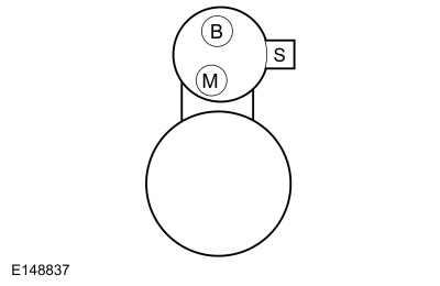 C197A-1 ("B" terminal)
|
|
C197B-1 ("S" terminal)
|
Did the starter engage and the engine crank?
| No
|
INSTALL a new starter motor.
REFER to:
Starter Motor
(303-06A Starting System - 1.6L Duratec-16V Ti-VCT (88kW/120PS) - Sigma, Removal and Installation).
|
|
| B23
CHECK FOR START INPUT AT THE STARTER
|
-
Install the
starter relay.
-
Disconnect Starter C197B-1 ("S"-terminal).
-
Press the Engine Start/Stop button and the brake or clutch pedal.
-
Measure:
|
Positive Lead
|
Measurement / Action
|
Negative Lead
|
|
C197B-1
|
|
Ground
|
Is the voltage greater than 11 volts?
| Yes
|
CLEAN the starter solenoid "S" terminal and starter solenoid connector. CHECK the wiring and the starter motor for a loose
or intermittent connection.
|
| No
|
REPAIR the circuit for an open.
|
|
| B24
CHECK THE PCM (POWERTRAIN CONTROL MODULE)
STARTER RELAY CIRCUITS FOR A SHORT TO GROUND
|
-
Measure:
|
Positive Lead
|
Measurement / Action
|
Negative Lead
|
|
C175E-15
|
|
Ground
|
|
C175E-32
|
|
Ground
|
Are the resistances greater than 10,000 ohms?
| No
|
REPAIR the affected circuit.
|
|
| B25
CHECK THE PCM (POWERTRAIN CONTROL MODULE)
STARTER RELAY CIRCUITS FOR AN OPEN
|
Are the resistances less than 3 ohms?
| No
|
REPAIR the affected circuit.
|
|
| B26
CHECK THE CRANK DETECT CIRCUIT FOR VOLTAGE AT THE PCM (POWERTRAIN CONTROL MODULE)
|
-
While pressing the Engine Start/Stop button, measure:
|
Positive Lead
|
Measurement / Action
|
Negative Lead
|
|
C175B-9
|
|
Ground
|
Is the voltage greater than 11 volts?
|
| B27
CHECK THE CPP (CLUTCH PEDAL POSITION)
SWITCH
|
-
While fully applying the clutch pedal, measure:
|
Positive Lead
|
Measurement / Action
|
Negative Lead
|
|
C175B-14
|
|
Ground
|
Is the resistance less than 3 ohms?
|
| B28
CHECK THE CPP (CLUTCH PEDAL POSITION)
GROUND CIRCUIT FOR AN OPEN
|
-
Disconnect
switch C2353
.
-
Measure:
|
Positive Lead
|
Measurement / Action
|
Negative Lead
|
|
C2353-2
|
|
Ground
|
Is the resistance less than 3 ohms?
|
| B29
CHECK THE CPP (CLUTCH PEDAL POSITION)
SWITCH CIRCUIT FOR AN OPEN
|
-
Measure:
|
Positive Lead
|
Measurement / Action
|
Negative Lead
|
|
C175B-14
|
|
C2353-1
|
Is the resistance less than 3 ohms?
|
| B30
CHECK THE CLUTCH BOTTOM TRAVEL CIRCUIT FOR A SHORT TO GROUND
|
-
Measure:
|
Positive Lead
|
Measurement / Action
|
Negative Lead
|
|
C175B-14
|
|
Ground
|
Is the resistance greater than 10,000 ohms?
|
| B31
CHECK FOR CORRECT PCM (POWERTRAIN CONTROL MODULE)
OPERATION
|
-
Disconnect and inspect all
connectors.
-
Repair:
-
corrosion (install new connectors or terminals - clean module pins)
-
damaged or bent pins - install new terminals/pins
-
pushed-out pins - install new pins as necessary
-
Reconnect the
connectors. Make sure they seat and latch correctly.
-
Operate the system and determine if the concern is still present.
Is the concern still present?
| Yes
|
CHECK
for any applicable Technical Service Bulletins (TSBs). If a
exists for this concern, DISCONTINUE this test and FOLLOW the
instructions. If no Technical Service Bulletins (TSBs) address this concern, INSTALL a new
.
REFER to:
Powertrain Control Module (PCM)
(303-14A Electronic Engine Controls - 1.6L Duratec-16V Ti-VCT (88kW/120PS) - Sigma, Removal and Installation).
|
| No
|
The system is operating correctly at this time. The concern may have been caused by module connections. ADDRESS the root cause
of any connector or pin issues.
|
|
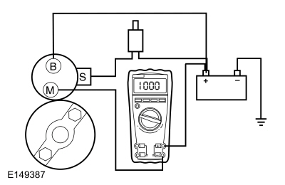
Correct starter operation relies on correct mounting of the starter to the engine, alignment of the starter ring gear to the
flexplate and correct functioning of the starter assembly (internal gears, bearings).
When the ignition is turned to the START position the
receives a voltage signal on the crank detect circuit. When the required inputs have been received, the
supplies voltage and ground to the starter relay coil.
The wake-up control circuit wakes up the
prior to engine cranking. The
needs to wake up prior to a crank request so it has time to go through its initialization. The wake-up control circuit is
controlled by the
. The
activates the wake-up control circuit when: the driver door is opened. a key is inserted into the ignition. or when the ignition
is in the ON or START position.
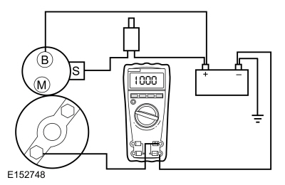
A slow cranking condition can be caused by resistance in the ground or return portion of the cranking circuit. This procedure
checks the voltage drop in the ground circuit.