23. CLUSTER
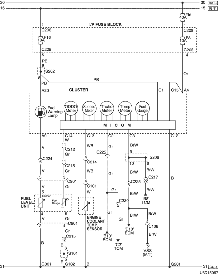
1) speedometer, fuel meter, temp. METER, TACHOMETER & ODOMETER CIRCUIT : MR-140
a. CONNECTOR INFORMATION
connector no
(pin no, color) |
connecting wiring harness |
connector position |
| C101 (15 Pin, Black) |
Engine – Front |
Behind the Left Headlamp |
| C102 (16 Pin, Black) |
Engine – Front |
Behind the Left Headlamp |
| C103 (6 Pin, Gray) |
Front – Engine |
Under the Engine Fuse Block |
| C205 (14 Pin, White) |
I/P Fuse Block – IP |
Front the I/P Fuse Block |
| C206 (3 Pin, Brown) |
I/P Fuse Block – IP |
Front the I/P Fuse Block |
| C209 (1 Pin, Colorless) |
I/P Fuse Block – Front |
Behind the I/P Fuse Block |
| C212 (18 Pin, Blue) |
Front – IP |
Left Upper the Driver Leg Room |
| C214 (26 Pin, Yellow) |
Front – IP |
Left Upper the Driver Leg Room |
| C215 (16 Pin, White) |
Floor – Front |
Under the I/P Fuse Block |
| C217 (22 Pin, White) |
IP – TCM |
Center Upper the Driver Leg Room |
| C224 (14 Pin, White) |
IP – Floor |
Under the Door Lock Unit |
| C901 (6 Pin, Black) |
Fuel Tank – Floor |
Behind the Fuel Tank |
| S201 (Colorless) |
Front |
Left Upper the Driver Leg Room |
| S202 (Orange) |
IP |
Rear Right Instrument Panel |
| S206 (Violet) |
IP |
Rear Left Instrument Panel |
| G201 |
IP |
Rear Right Instrument Panel |
| G301 |
Floor |
Under the Driver Room Floor |
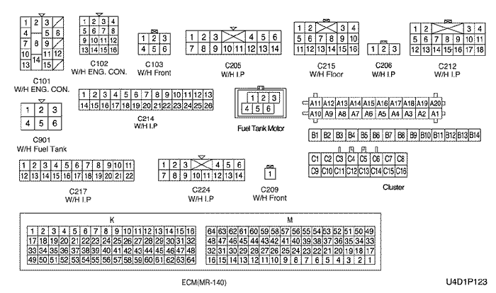
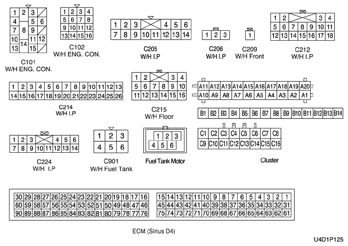
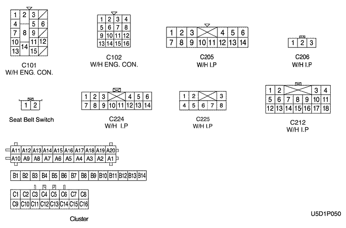
b. CONNECTOR IDENTIFICATION SYMBOL & PIN NUMBER POSITION
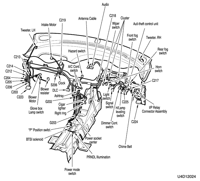
c. POSITION OF CONNECTORS AND GROUNDS
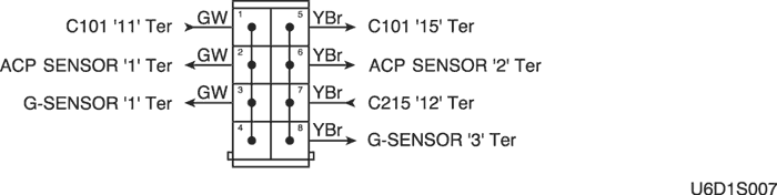
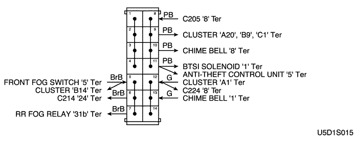
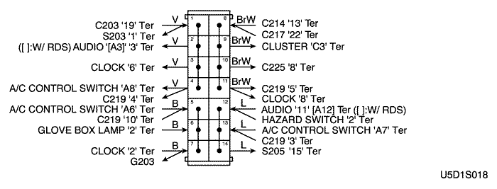
d. SPLICE PACK
s201 (mr-140)
s202
s206
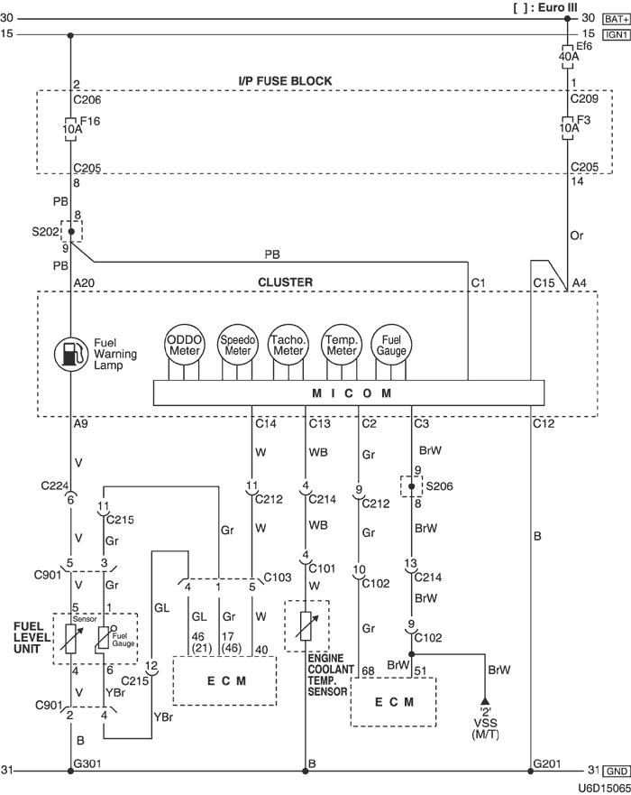
2) speedometer, fuel meter, temp. METER, TACHOMETER & ODOMETER CIRCUIT : SIRIUS D4 (EOBD)
a. CONNECTOR INFORMATION
connector no
(pin no, color) |
connecting wiring harness |
connector position |
| C101 (15 Pin, Black) |
Engine – Front |
Behind the Left Headlamp |
| C102 (16 Pin, Black) |
Engine – Front |
Behind the Left Headlamp |
| C103 (6 Pin, Gray) |
Front – Engine |
Under the Engine Fuse Block |
| C205 (14 Pin, White) |
I/P Fuse Block – IP |
Front the I/P Fuse Block |
| C206 (3 Pin, Brown) |
I/P Fuse Block – IP |
Front the I/P Fuse Block |
| C209 (1 Pin, Colorless) |
I/P Fuse Block – Front |
Behind the I/P Fuse Block |
| C212 (18 Pin, Blue) |
Front – IP |
Left Upper the Driver Leg Room |
| C214 (26 Pin, Yellow) |
Front – IP |
Left Upper the Driver Leg Room |
| C215 (16 Pin, White) |
Floor – Front |
Under the I/P Fuse Block |
| C224 (14 Pin, White) |
IP – Floor |
Under the Door Lock Unit |
| C901 (6 Pin, Black) |
Fuel Tank – Floor |
Behind the Fuel Tank |
| S202 (Orange) |
IP |
Rear Right Instrument Panel |
| S206 (Violet) |
IP |
Rear Left Instrument Panel |
| G201 |
IP |
Rear Right Instrument Panel |
| G301 |
Floor |
Under the Driver Room Floor |
b. CONNECTOR IDENTIFICATION SYMBOL & PIN NUMBER POSITION
c. POSITION OF CONNECTORS AND GROUNDS
d. SPLICE PACK
s202
s206
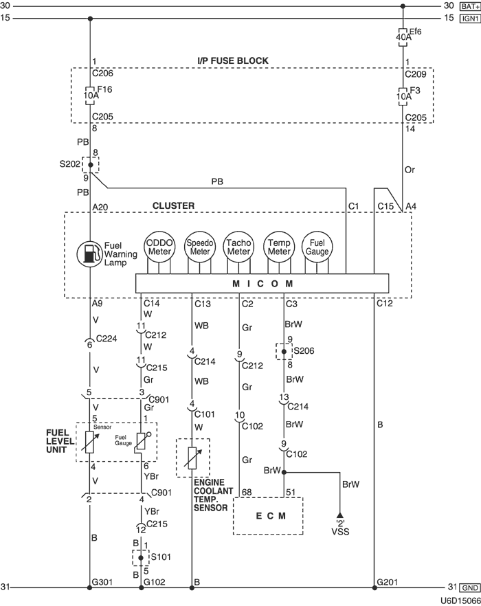
3) speedometer, fuel meter, temp. METER, TACHOMETER & ODOMETER CIRCUIT : SIRIUS D4 (NON EOBD)
a. CONNECTOR INFORMATION
connector no
(pin no, color) |
connecting wiring harness |
connector position |
| C101 (15 Pin, Black) |
Engine – Front |
Behind the Left Headlamp |
| C102 (16 Pin, Black) |
Engine – Front |
Behind the Left Headlamp |
| C205 (14 Pin, White) |
I/P Fuse Block – IP |
Front the I/P Fuse Block |
| C206 (3 Pin, Brown) |
I/P Fuse Block – IP |
Front the I/P Fuse Block |
| C209 (1 Pin, Colorless) |
I/P Fuse Block – Front |
Behind the I/P Fuse Block |
| C212 (18 Pin, Blue) |
Front – IP |
Left Upper the Driver Leg Room |
| C214 (26 Pin, Yellow) |
Front – IP |
Left Upper the Driver Leg Room |
| C215 (16 Pin, White) |
Floor – Front |
Under the I/P Fuse Block |
| C224 (14 Pin, White) |
IP – Floor |
Under the Door Lock Unit |
| C901 (6 Pin, Black) |
Fuel Tank – Floor |
Behind the Fuel Tank |
| S101 (White) |
Front |
Inside the Engine Fuse Block |
| S202 (Orange) |
IP |
Rear Right Instrument Panel |
| S206 (Violet) |
IP |
Rear Left Instrument Panel |
| G102 |
Front |
Behind the Left Headlamp |
| G201 |
IP |
Rear Right Instrument Panel |
| G301 |
Floor |
Under the Driver Room Floor |
b. CONNECTOR IDENTIFICATION SYMBOL & PIN NUMBER POSITION
c. POSITION OF CONNECTORS AND GROUNDS
d. SPLICE PACK
s101
s202
s206
4) speedometer, fuel meter, temp. METER, TACHOMETER & ODOMETER CIRCUIT : ITMS-6F
a. CONNECTOR INFORMATION
connector no
(pin no, color) |
connecting wiring harness |
connector position |
| C101 (15 Pin, Black) |
Engine – Front |
Behind the Left Headlamp |
| C106 (16 Pin, Black) |
Engine – ECM |
Right Upper The Driver Leg Room |
| C205 (14 Pin, White) |
I/P Fuse Block – IP |
Front the I/P Fuse Block |
| C206 (3 Pin, Brown) |
I/P Fuse Block – IP |
Front the I/P Fuse Block |
| C209 (1 Pin, Colorless) |
I/P Fuse Block – Front |
Behind the I/P Fuse Block |
| C212 (18 Pin, Blue) |
Front – IP |
Left Upper the Driver Leg Room |
| C214 (26 Pin, Yellow) |
Front – IP |
Left Upper the Driver Leg Room |
| C215 (16 Pin, White) |
Floor – Front |
Under the I/P Fuse Block |
| C217 (22 Pin, White) |
IP – TCM |
Center Upper the Driver Leg Room |
| C220 (6 Pin, White) |
ECM - TCM |
Right Center the Driver Leg Room (ITMS–6F) |
| C224 (14 Pin, White) |
IP – Floor |
Under the Door Lock Unit |
| C225 (8 pin, White) |
IP – ECM |
Center Upper The Driver Leg Room |
| C901 (6 Pin, Black) |
Fuel Tank – Floor |
Behind the Fuel Tank |
| S101 (White) |
Front |
Inside the Engine Fuse Block |
| S202 (Orange) |
IP |
Rear Right Instrument Panel |
| S206 (Violet) |
IP |
Rear Left Instrument Panel |
| G102 |
Front |
Behind the Left Headlamp |
| G201 |
IP |
Rear Right Instrument Panel |
| G301 |
Floor |
Under the Driver Room Floor |
b. CONNECTOR IDENTIFICATION SYMBOL & PIN NUMBER POSITION
c. POSITION OF CONNECTORS AND GROUNDS
d. SPLICE PACK
s101
s202
s206
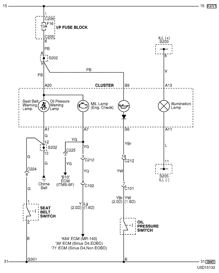
5) warning (seat belt, oil pressure & mil) lamp & illumination lamp circuit
a. CONNECTOR INFORMATION
connector no
(pin no, color) |
connecting wiring harness |
connector position |
| C101 (15 Pin, Black) |
Engine – Front |
Behind the Left Headlamp |
| C102 (16 Pin, Black) |
Engine – Front |
Behind the Left Headlamp |
| C205 (14 Pin, White) |
I/P Fuse Block – IP |
Front the I/P Fuse Block |
| C206 (3 Pin, Brown) |
I/P Fuse Block – IP |
Front the I/P Fuse Block |
| C212 (18 Pin, Blue) |
Front – IP |
Left Upper the Driver Leg Room |
| C224 (14 Pin, White) |
IP – Floor |
Under the Door Lock Unit |
| C225 (8 pin, White) |
IP – ECM |
Center Upper The Driver Leg Room |
| S202 (Orange) |
IP |
Rear Right Instrument Panel |
| S203 (Orange) |
IP |
Rear Center Instrument Panel |
| S205 (Orange) |
IP |
Rear Center Instrument Panel |
| G301 |
Floor |
Under the Driver Room Floor |
b. CONNECTOR IDENTIFICATION SYMBOL & PIN NUMBER POSITION
c. POSITION OF CONNECTORS AND GROUNDS
d. SPLICE PACK
s202
s203
s205
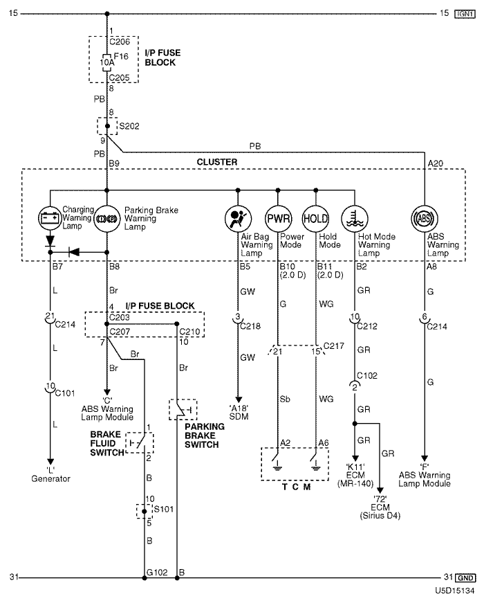
6) warning (charging, parking brake, abs, air-bag, power mode, hold mode & hot mode) lamp circuit
a. CONNECTOR INFORMATION
connector no
(pin no, color) |
connecting wiring harness |
connector position |
| C101 (15 Pin, Black) |
Engine – Front |
Behind the Left Headlamp |
| C102 (16 Pin, Black) |
Engine – Front |
Behind the Left Headlamp |
| C203 (22 Pin, White) |
I/P Fuse Block – IP |
Front the I/P Fuse Block |
| C205 (14 Pin, White) |
I/P Fuse Block – IP |
Front the I/P Fuse Block |
| C206 (3 Pin, Brown) |
I/P Fuse Block – IP |
Front the I/P Fuse Block |
| C207 (22 Pin, White) |
I/P Fuse Block – Front |
Behind the I/P Fuse Block |
| C210 (18 Pin, White) |
I/P Fuse Block – Floor |
Behind the I/P Fuse Block |
| C212 (18 Pin, Blue) |
Front – IP |
Left Upper the Driver Leg Room |
| C214 (26 Pin, Yellow) |
Front – IP |
Left Upper the Driver Leg Room |
| C217 (22 Pin, White) |
IP – TCM |
Center Upper the Driver Leg Room |
| C218 (4 Pin, White) |
Air Bag – IP |
Right Upper the Driver Leg Room |
| S101 (White) |
Front |
Inside the Engine Fuse Block |
| S202 (Orange) |
IP |
Rear Right Instrument Panel |
| G102 |
Front |
Behind the Left Headlamp |
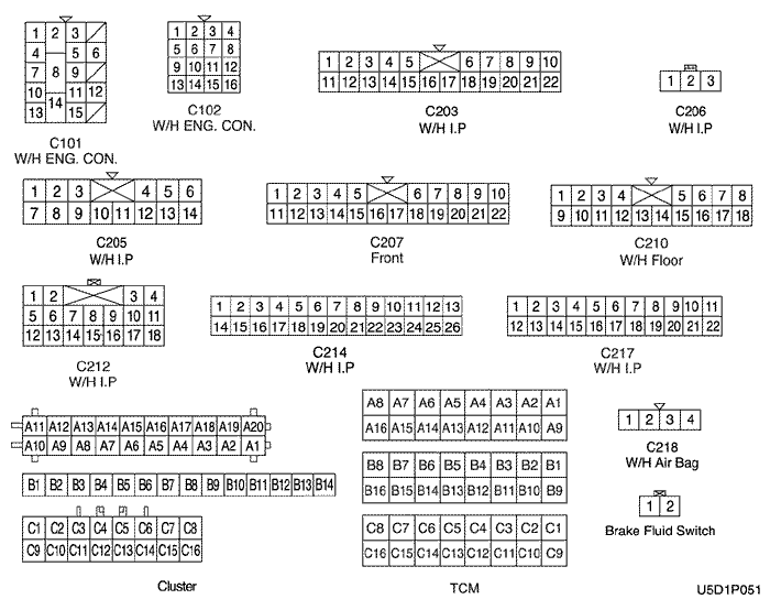
b. CONNECTOR IDENTIFICATION SYMBOL & PIN NUMBER POSITION
c. POSITION OF CONNECTORS AND GROUNDS
d. SPLICE PACK
s101
s202
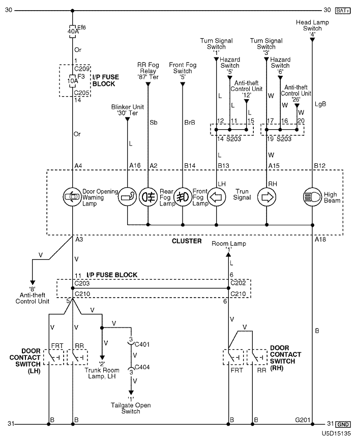
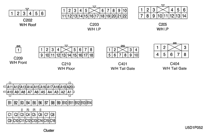
7) indicator (turn signal, front/rear fog, door opening warning & high beam) lamp circuit
a. CONNECTOR INFORMATION
connector no
(pin no, color) |
connecting wiring harness |
connector position |
| C202 (6 Pin, White) |
I/P Fuse Block – Roof |
Front the I/P Fuse Block |
| C203 (22 Pin, White) |
I/P Fuse Block – IP |
Front the I/P Fuse Block |
| C205 (14 Pin, White) |
I/P Fuse Block – IP |
Front the I/P Fuse Block |
| C209 (1 Pin, Colorless) |
I/P Fuse Block – Front |
Behind the I/P Fuse Block |
| C210 (18 Pin, White) |
I/P Fuse Block – Floor |
Behind the I/P Fuse Block |
| C401 (10 Pin, White) |
Tailgate – Floor |
Behind the Rear Quarter Glass |
| C404 (8 Pin, White) |
Tailgate – Tailgate, AUX |
Left Under Tailgate Behind the Tail Lamp |
| S203 (Orange) |
IP |
Rear Center Instrument Panel |
| G201 |
IP |
Rear Right Instrument Panel |
b. CONNECTOR IDENTIFICATION SYMBOL & PIN NUMBER POSITION
c. POSITION OF CONNECTORS AND GROUNDS
d. SPLICE PACK
s203
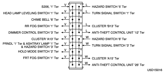
8) indicator & prnd switch
a. CONNECTOR INFORMATION
connector no
(pin no, color) |
connecting wiring harness |
connector position |
| C203 (22 Pin, White) |
I/P Fuse Block – IP |
Front the I/P Fuse Block |
| C206 (3 Pin, Brown) |
I/P Fuse Block – IP |
Front the I/P Fuse Block |
| C217 (22 Pin, White) |
IP – TCM |
Center Upper the Driver Leg Room |
b. CONNECTOR IDENTIFICATION SYMBOL & PIN NUMBER POSITION
c. POSITION OF CONNECTORS AND GROUNDS
| https://vnx.su/ 🛠 Руководства по ремонту и эксплуатации для автомобилей |
Поиск по сайту
Остались вопросы или пожелания? Пишите на почту: support@vnx.su