SECTION 5
electrical wiring diagrams
1. STARTING & CHARGING SYSTEM
1) battery, ignition switch, pnp switch, starter motor & generator circuit: mr-140, sirius d4
a. CONNECTOR INFORMATION
connector no
(pin no, color) | connecting wiring harness | connector position |
| C101(15 Pin, Black) | Engine – Front | Behind the Left Headlamp |
| C105 (4 Pin, White) | TCM – Engine | Rear Intake Manifold |
| C205 (14 Pin, White) | I/P Fuse Block – IP | Front the I/P Fuse Block |
| C206 (3 Pin, Brown) | I/P Fuse Block – IP | Front the I/P Fuse Block |
| C208 (14 Pin, White) | I/P Fuse Block – Front | Behind the I/P Fuse Block |
| C213 (7 Pin, Gray) | Front – IP | Left Upper the Driver Leg Room |
| C214 (26 Pin, Yellow) | Front – IP | Left Upper the Driver Leg Room |
| C217 (22 Pin, White) | IP – TCM | Center Upper the Driver Leg Room |
| S102 (Black) | Engine | Rear Intake Manifold |
| S202 (Orange) | IP | Rear Right Instrument Panel |
| G101 | Battery | Behind the Battery |
| G104 | Engine | Under the Intake Manifold |
| G106 | Battery | Under the Starter Motor Mounting Bolt |
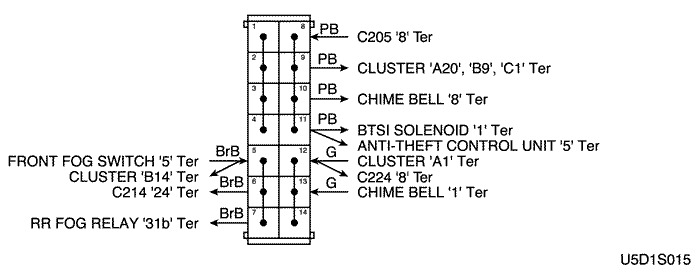
b. CONNECTOR IDENTIFICATION SYMBOL & PIN NUMBER POSITION
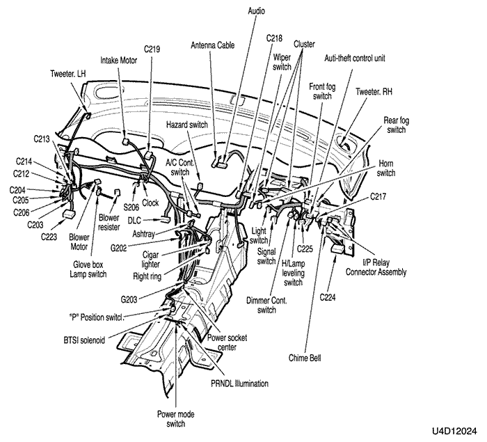
c. POSITION OF CONNECTORS AND GROUNDS
d. SPLICE PACK
s102 (mr-140)
s102 (sirius d4)
s202
2) battery, ignition switch, pnp switch, starter motor & generator circuit: itms-6f
a. CONNECTOR INFORMATION
connector no
(pin no, color) | connecting wiring harness | connector position |
| C101(15 Pin, Black) | Engine – Front | Behind the Left Headlamp |
| C107 (16 Pin, Black) | Engine – ECM | Ringt Upper the Driver Leg Room |
| C205 (14 Pin, White) | I/P Fuse Block – IP | Front the I/P Fuse Block |
| C206 (3 Pin, Brown) | I/P Fuse Block – IP | Front the I/P Fuse Block |
| C208 (14 Pin, White) | I/P Fuse Block – Front | Behind the I/P Fuse Block |
| C213 (7 Pin, Gray) | Front – IP | Left Upper the Driver Leg Room |
| C214 (26 Pin, Yellow) | Front – IP | Left Upper the Driver Leg Room |
| C217 (22 Pin, White) | IP – TCM | Center Upper the Driver Leg Room |
| C220 (6 Pin, White) | ECM – TCM | Right Center the Driver Leg Room |
| S201 (Colorless) | ECM | Left Upper the Driver Leg Room |
| S202 (Orange) | IP | Rear Right Instrument Panel |
| G101 | Battery | Behind the Battery |
| G104 | Engine | Under the Intake Manifold |
| G106 | Battery | Under the Starter Motor Mounting Bolt |
b. CONNECTOR IDENTIFICATION SYMBOL & PIN NUMBER POSITION
c. POSITION OF CONNECTORS AND GROUNDS
d. SPLICE PACK
s201 (itms-6f)
s202
sm
| https://vnx.su/ 🛠 Руководства по ремонту и эксплуатации для автомобилей |
Поиск по сайту
Остались вопросы или пожелания? Пишите на почту: support@vnx.su